
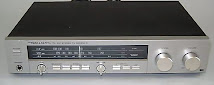
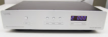
The legendary IC-R71 communications receiver in all it's guises, A/E/D was as much loved as it was disliked by many. With it's short comings aside it's performance was extremely good for it's time and was classed as a top performance receiver. Amongst the drawbacks were a very inefficient and warm running AC power supply causing allot of heat to be generated which was not healthy for electronics in general, the failing memory unit due to the failing of the back up lithium battery after 7-10 years of operation dependant on the location of operation causing the set to loose retention of all memories and render the set inoperable until it was reset was also a major issue. Of course there was also the main complaint of the lousy AM audio of the set, it was muddy and basically not something you wanted to listen to for a long while.

On the other side of the spectrum, it won tremendous acclaim for being a very sensitive and selective receiver with uncompromising SSB performance which was a joy to listen to. SSB reception was completely the opposite of AM. Great if you were only going to use it for Amateur Radio reception. The rx architecture of this unit is a quadruple super hetrodyne design on AM/CW/SSB and triple super hetrodyne on FM. The model was made Japan between 1984-1996. In those days the set was also the main competitor of the JRC NRD525. The main failing as with the older 525 was the noisy AF amplifier.
 The IF frequencies are 70.4515MHz, 9.0115MHz, 455KHz and 9.0115MHz (This last IF is not used on F3). The second IF center frequency is :
SSB (A3J), AM (A3): 9.0115MHz
CW (A1), RTTY (F1): 9.0106MHz
FM (F3): 9.0100MHz
It has a very high dynamic range of 105dB.
Features included a ¼" Head. Jack, S-Meter, PBT, Preamp, IF Notch, AGC, BFO, Tone, Preamp, Dual VFOs, Squelch, Dimmer, 32 Memories, Attenuator, Squelch, Keypad, Dial Tension Adjust, Lock. Accessories for the receiver included the FL-63 CW Filter, FL-44A SSB Filter, EX-257 FM Mode Option, CR-64 High Stability, EX-309 Interface Option, CT-17 Level Converter, UX-14 CI-IV/CI-V Converter, MB-12 Mobile Bracket, EX-310 Voice Synthesizer.
Even so many of these sets were commissioned by various government agencies around the world into professional use in embassies as well as the nudge, nudge, wink, wink three lettered ops. On the VHF-SHF side, this set was partnered up with it's brother the IC-R7000 and the couple made a formidable set up.
Many people went to great lengths to improve upon the AM performance of the IC-R71 by changing speakers, capacitors and filters and amongst these was a company called Kiwa, who still serve the SWL/BCL and ham community today with their wide range of modifications for a select number of radio receivers. Kiwa had some AF upgrade kits and AM replacement filters which replace the stock Icom AM filter. The premium of the Kiwa AM filters was known as the "Blue Dot" which I have installed in my own R71E.
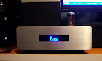
Over the weeks to come I will add more photos and details on my own R71E here. My R71 found it's way to me from Jilin, China:
 WILLCO ELECTRONICS NO-FAIL MEMORY FOR ICOM RADIOSThe Willco Electronics "No-Fail" Memory For Icom R71 (info. from Willco):
WILLCO ELECTRONICS NO-FAIL MEMORY FOR ICOM RADWhen Icom made the R71 they selected the RAM based system to support multiple versions for shipment to other countries. In the mid 80's, small inexpensive RAM memory chips were available and before shpping the radio, Icom used computer controlled programming fixtures to load the memory module with the appropriate version. Back then 32K EPROM's carried a high price tag and low power, battery backed, 32K Random Access Memories were not available.
WILLCO ELECTRONICS NO-FAIL MEMORY FOR ICOM RADIOSThe Willco Electronics "No-Fail" Memory For Icom R71 (info. from Willco):
WILLCO ELECTRONICS NO-FAIL MEMORY FOR ICOM RADWhen Icom made the R71 they selected the RAM based system to support multiple versions for shipment to other countries. In the mid 80's, small inexpensive RAM memory chips were available and before shpping the radio, Icom used computer controlled programming fixtures to load the memory module with the appropriate version. Back then 32K EPROM's carried a high price tag and low power, battery backed, 32K Random Access Memories were not available. The lithium battery had a projected life expectancy of 10 years and some batteries, at room temperature, can last longer than 15 years. Unfortunately, Hams don't always operate their equipment at room temperature. Depending on the environment, mobile or portable operation for example, the battery life can be reduced.
The Willco ICM-1024B "NO FAIL" memory is a replacement memory module that contains a Read Only Memory (ROM) that permanently stores the radio's important data and a battery backed Random Access Memory (RAM) that stores the radio's 32 (or 1024) memories. So I ordered the ICM-1024B "No Fail" memory replacement module from Willco and await it's arrival. Below is a photo of the board compared to the original Icom board:

ICOM R-71A Processor Noise Cure *Author:* Burt Weiner, K6OQK
I've bought my ICOM R-71A approximately 20 years ago. I use the radio mainly as a detector in making heterodyne type frequency measurements, particularly in the AM broadcast band. Part of my setup requires a step attenuator between the antenna and the input to the radio. It is a great radio with one exception: from the day I bought the R-71A there has been an internally generated digital type noise, particularly in and around the broadcast band. This digital noise became particularly noticeable whenever I would switch in 20 dB or more of external attenuation. I learned to live with it.
Recently the battery on the memory board died taking the radio's mind with it. I replaced the memory board with a Willco Electronics ICM-1024 "No Fail Memory" board. I can highly recommend Willco's replacement board. While I had the radio opened I decided I was going to try and locate the source of the digital noise and see if I could shield whatever was radiating it. Actually the cure turned out to be a lot simpler than I had imagined it was going to be. The noise was being picked up by a small grey coaxial cable running across the front of the radio just behind the top of the front panel where it is held in place by two pieces of clear tape.
First you will have to remove the top and bottom covers from the radio. Set the radio so that the front panel is facing you as it would in normal use. Once you've done this you will see the small grey cable that is held in place with clear tape at the top rear of the front panel. This cable runs from the circuit board on the left side of the radio, across the front panel to the circuit board on the right side of the radio. The cable is soldered onto the left side board but it is plugged into the right side board.
The cure was simply a matter of unplugging the cable from the right side board, feeding it backwards out across the front panel all the way to the left side and then re-dressing it under the radio, past the accessory panel and back to the right side board and plugging it back in from whence it came. Be sure not to dress it over the edges of the chassis where the bottom cover will pinch it.
There are some access slots in the bottom of the side compartments where you can dress the cable to avoid it being pinched once the covers are placed back on the radio. The cable is just long enough so that it can be properly dressed along the new path without placing any strain on it. Since re-routing this cable there is absolutely no sign of the digital noise that had plagued me for lo these many years. Burt Weiner, K6OQK
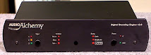
 i5xww DRM converter 9.0106 MHz to 12 KHz for ICOM radios:
Not only for DRM reception! With the free softwares available in the internet this converter permits use of variable bandwitdh digital filters, signals within plus or minus 12 kHz can be watched on a spectrum analyzer window and, for example, listening to two or more different stations (also in different modes AM, SSB, CW, FM) can be performed by running in more instances with SDRadio software.
To receive DRM broadcasting stations a downconverter from 455 to 12 kHz is commonly used, tapping the signal off a radio IF circuit and processing it by freely available software.. Even if some Icom radios include circuits at both 9 MHz and 455 kHz, most of them are based on a single IF at 9 MHz. 
This converter can be connected to where an optional filter would have been fitted (often a two-pole jack is available for the optional filter to be dropped in, requiring so no soldering to the radio) . As standard it takes up the place of a narrow CW filter and so it is already adjusted for a 9.0106 MHz to 12 kHz conversion. Its output at 12 kHz will be connected to a PC soundcard (either Line-in or Mic inputs) It will be powered from the radio or from a separate power supply / battery at 9 to 12 V. Then you can run the Dream software (freely downloadable from the internet) taking care to check the "Flip Input Spectrum“ box in the Evaluation Dialog window (Ctrl+E). 
You are now in business for tuning in DRM radio stations and listen to their high quality digital programs. Normally you first tune in a station using either the AM or SSB filter (also for checking the strength of the received signal), then you select for ex. the CWN filter, i.e. the same would-be filter this converter replaces Normal audio will not be available any more from the radio speaker and the S-meter will not work. Instead you will decode the received signals by means of the Dream software. This will include DRM stations as well as AM, SSB, CW, FM stations. More software is available (either freely or paid for) to decode these signals using their advanced digital filter processing at 12 kHz (full control of bandwith etc.). The converter include an input white/blue trimmer which is normally set at its maximum. You will also need to adjust settings of the Windows mixer to select signal input (Line-in or Mic) and its level. This converter is supplied already adjusted for a 9.0106 MHz to 12 kHz conversion as most of the times it is connected to the same pins (soldered or plugged in) where an optional narrow CW filter would be placed. There is a black capacitive trimmer on board which should be set for a 9.0115 MHz to 12 kHz in case the converter takes up the place of an SSB filter. This trimming is easily done when one looks at the converted frequency between 0 and 24 khz of the spectrum analyzer within the Dream software. This trimming is important when a CAT cable is used for remote controlling of the radio as DRM stations may be correctly tuned in by clicking on a frequency list within the Dream software. DRM stations may also be easier tuned by selecting them from a list inside the Dream software by the use of a suitable CAT cable. Detailled information about fitting this converter inside or outside the radio is not given. The addition of such converters to some models of radios is detailed on the official pages of the DRM organization as well as on pages that some amateurs publish to share their experiences. This board measures 36.5 x 22.7 mm (1 7/16 x just over 7/8") DRM Introduction: Digital Radio Mondiale (DRM) is a digital radio system for short-wave, AM / medium-wave and long-wave. It has been endorsed by the ITU, IEC and ETSI. DRM currently covers the broadcasting bands below 30 MHz. The quality of DRM audio is excellent, and the improvement upon analogue AM is immediately noticeab...le. Besides providing near-FM quality audio, the DRM system has the capacity to integrate data and text.
The DRM signal is designed to fit in with the existing AM broadcast band plan, based on signals of 9 kHz or 10kHz bandwidth. The DRM system uses a type of transmission called COFDM (Coded Orthogonal Frequency Division Multiplex). This means that all the data, produced from the digitally encoded audio and associated data signals, is shared out for transmission across a large number of closely spaced carriers. All of these carriers are contained within the allotted transmission channel.
The DRM system is designed so that the number of carriers can be varied, depending on factors such as the allotted channel bandwidth and degree of robustness required. The DRM system can use three different types of audio coding, depending on broadcasters' preferences. MPEG4 AAC audio coding, augmented by SBR bandwidth extension, is used as a general-purpose audio coder and provides the highest quality. MPEG4 CELP speech coding is used for high quality speech coding where there is no musical content. HVXC speech coding can be used to provide a very low bit-rate speech coder. The robustness of the DRM signal can be chosen to match different propagation conditions.
All you need to receive DRM transmissions is a PC with a sound card and a modified analog short-wave (MW, LW) receiver. The Icom IC-R71 fitted with the DRM converter produces the 12kHz DRM signal that is fed to the microphone input on the computers sound card. Finally, you will need some software [DReaM] to decode the DRM signal and the good news is ... it's FREE!!
|
Other Loaded Options:
|
| Center Frequency: | 9.0115MHz
|
| Bandwidth: | 2.8KHz / -6dB, (5KHz / -60dB) |
| Shape Factor:
| 1.79
|
| Brand / Type: | Icom FL-70 SSB Wide Filter
|
| Pic: |
 |
1. Icom FL-70 SSB Wide Crystal Filter 9.0115MHz (2.8KHz / -6dB),
(5KHz / -60dB), Shape Factor 1.79
| Center Frequency: | 455kHz |
| Bandwidth: | 2.4kHz @ -6dB |
| Passband Ripple: | 2dB |
| Input Impedance: | 2k Ohm |
| Output Impedance: | 2k Ohm |
2. 2.4kHz/-6dB Murata ceramic filter (CFJ455K6) in the narrow position.
|
| Center Frequency: | 9.0115MHz
|
| Bandwidth: | 2.3KHz/-6dB
|
|
|
|
| Brand/Type:
| Icom FL-30 Medium SSB Filter
|
| Pic: | |
3. ICOM FL-30 SSB Filter 9.0115 Mhz (2.3KHz/ -6dB).
Mod Log:
19/12/2009:
a. Replaced power supply elec. caps with 2 x 470uF 50V low ESR 105deg. C, 1 x 100uF 50V Elna "Silmic II" audio grade, 1 x 4,700uF, 50V Nichicon "Muse" audio grade.
About Elna Silmic II Capacitors:
The SILMIC series are Elna's highest grade audio capacitors that exhibit superior acoustic characteristics. An entirely new type of electrolytic separating paper is used, containing silk fibers. The extreme softness of silk can mitigate vibrational energy (generated by the electrodes, by external vibrations and by electromagnetic fields). Due to it's new electrolytic and foil design the signal propagation speed has increased (the ESR is reduced) and a more powerful, yet-mellow, sound is possible than before. When these capacitors were subjected to aural evaluations, the high range peak and midrange roughness were reduced substantially. Also, the low range richness and power were increased in the obtained high-quality sound.
Silmic II info PDF
Nichicon "Muse" 4,700uF FW Elec. Capacitor:
| - Capacitance |
Tolerance: ±20% at 120Hz, 20°C Leak Current: After 1 minutes application of rated voltage,
leakage current is 0.01CV or less |
|
| - Tanδ: ≤0.12 |
| - Temperature Range: -40°C ~ 85°C |
| - Dimensions: Φ20mm x 40mm(Diameter x Height), Pitch 10mm, 1mm tinned copper wire |
|
| - Quality: New; Year of Production 2008; Adapted to the RoHS directive (2002/95/EC) |
|
| - Features: |
| 1. Premium grade "nichicon FW MUSE" acoustic series. |
| 2. Ideally suited for first class audio equipment where high quality is required. |
Nichicon "Muse" FW Details PDF
b. Installed Icom FL-70 Wide SSB Filter, Icom FL-30 SSB Filter, 2.4kHz/-6dB Murata ceramic filter (CFJ455K6) in the narrow position.


IC-R71 -HF Base Receiver |
|
Quick Specs:
HF base receiver
RX: 0.1 MHz-30 MHz
TX: N/A
Output power: N/A
Modes: SSB, CW, AM, RTTY; FM (optional)
Receiver sensitivity: see the detailed specification |
|
Detailed Specifications
GENERAL
- Frequency Coverage: 0.1000-30.0000 MHz
- Modes: SSB(A3), CW(A1), RTTY (F1), FM(F3)*
- Tuning Step Increment: 10 Hz or 1 kHz
- Power Supply Requirement: 117 V AC +/-10%
- Usable Temperature Range: -10deg.C-+60deg.C (+14deg.F-+140deg.F)
- Dimensions:
- 286(W) x 110(H) x 276(D) mm
- 11.3(W) x 4.3(H) x 10.9(D) in (projections are not included)
- Weight: 7.5 kg; 16.5 lbs.
- Sensitivity:
- 0.1000-0.4999 MHz; SSB, CW, RTTY Less than 0.32 µV for 10 dB S/N; AM Less than 1.0 µV for 10 dB S/N
- 0.5000-1.5999 MHz; SSB, CW, RTTY Less than 1.0 µV for 10 dB S/N; AM Less than 3.2 µV for 10 dB S/N
- 1.6000-30.0000 MHz; SSB, CW, RTTY Less than 0.16 µV for 10 dB S/N; AM Less than 0.5 µV for 10 dB S/N; FM* Less than 0.32 µV for 12 dB SINAD (* with the optional IC-EX257 FM Unit)
- Selectivity (preamp ON):
- SSB, CW, RTTY, More than 2.3 kHz/-6 dB; Less than 4.2 kHz/-60 dB
- AM, More than 6 kHz/-6 dB; Less than 15 kHz/-50 dB
- FM*, More than 15 kHz/-6 dB; Less than 25 kHz/-60 dB (* with the optional IC-EX257 FM Unit)
- Audio Output Power: More than 3W at 10% distortion with an 8 ohm load
IC-R71 Options
- CT-17, CI-V Level Converter: for remote control using a personal computer with an RS-232C socket. An optional UX-14 is necessary for the IC-R71A
- EX-310, Voice Synthesizer Unit: Provides audible, synthesized readings for frequencies in English.
- IC-MB12, Mobile Mounting Bracket: receiver bracket for mobile operation.
- SP-3, External Speaker: External speaker. Matching style and size with the IC-7000 and IC-R71A
- SP-7, External Speaker: Compact external speaker.
- SP-20, External Speaker with audio Filters: High performance speaker with audio filters for greater sound quality.
- CR-64, High-Stability Crystal Unit: Contains a temperature-compensating oven heater and crystal unit for improved frequency stability. Frequency stability is +/-0.5 ppm (-10deg.C-+60deg.C;+14deg.F-+140deg.F)
- CT-16, Satellite Interface Unit: Easy tuning for instant satellite communications with the IC-R71 and an Icom transceiver. Optional UX-14 is necessary.
- IC-EX257, FM UNIT: Adds FM mode capability.
- FL-32A: CW and RTTY Narrow Filter (9.0106 MHz, 500 Hz/-6 dB)
- FL-63A, CW and RTTY Narrow Filter (9.0106 MHz, 250 Hz/-6 dB): Have good shape factors and provide you with better CW and RTTY reception.
- RC-11, Wireless Remote Controller: Infrared remote controller for effortless receiver control.
- UX-14, CI-IV/CI-V Converter: Allows you to use the CT-16 or CT-17.
|


 The IF frequencies are 70.4515MHz, 9.0115MHz, 455KHz and 9.0115MHz (This last IF is not used on F3). The second IF center frequency is :


No comments:
Post a Comment